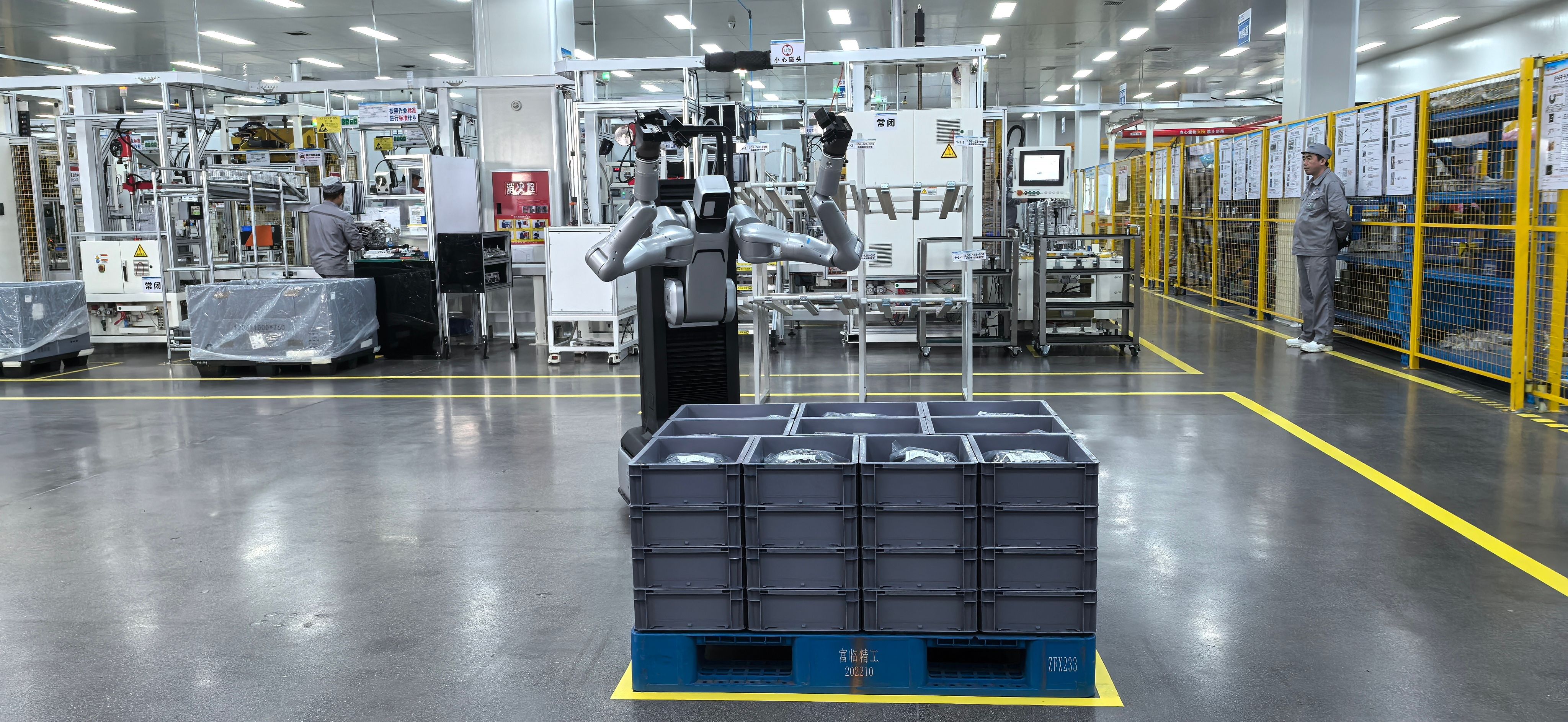
Wheeled Humanoid Robot Motion Control System
Open · Efficient · Intelligent
Document version: V1.0 Hardware platform: iNexBot industrial robot controller (RK3588 platform) Application areas: dual-arm collaboration, human-robot collaboration, robot algorithm validation, multi-robot coordinated control, advanced control theory research, industrial manufacturing, healthcare, commercial services, logistics and warehousing, education and research
1. Company Introduction
iNexBot Technology is a technology company focused on the R&D of robot motion control systems. With independently developed advanced control algorithms and extensive industry experience, it is committed to bringing wheeled humanoid robot technology into industrial and service applications. The iNexBot motion control system delivers precise control of key body parts such as the dual arms, waist and neck, giving robots exceptional flexibility and adaptability.
2. Product Overview
The iNexBot Technology wheeled humanoid robot motion control system is designed for complex scenarios and supports multiple configuration options to meet diverse application needs. The platform is built on the ABOX-6116 industrial controller (Rockchip RK3588 + Debian 11 / Ubuntu 20.04) and ships standard with dual robot control engines (14 axes or 12 axes total, expandable up to 32 axes). It exposes the full-chain NexDroid OpenAPI, allowing users to develop their own algorithms end to end, from the joint control layer up to trajectory planning. The modular design offers strong compatibility and seamless integration with third-party wheel bases, dexterous hands and vision systems.
The platform targets universities, research institutes and corporate laboratories, providing a high-realtime, highly open hardware foundation and software ecosystem for research scenarios such as dual-arm coordinated motion control, advanced dynamics algorithms and intelligent control strategies, as well as real-world industrial and service deployments.
3. Product Features
3.1 Dual-Arm Collaborative Control System
- Supports two dual-arm configurations:
- Dual 6-axis collaborative robots (2×6 axes)
- Dual 7-axis collaborative robots (2×7 axes)
- 7-axis configuration: the wrist supports SRS structures (spherical-revolute-spherical) or cross-intersecting structures, flexibly selectable according to the task
- High-precision trajectory planning and collision detection
- Dual-arm collaborative operation modes supporting:
- Symmetric synchronized motion
- Asymmetric coordinated manipulation
- Object handover and transfer
- Hybrid force-position control
3.2 Waist Control System
- Multiple configuration options:
- 1 axis (rotation)
- 3 axes (X/Y/Z translation)
- 4 axes (4 serial joints)
- 6 axes (3 translation + 3 rotation)
- Dynamic balance compensation
- Load-adaptive capability
3.3 Neck Control System
- Single-axis rotation design
- Expandable to multi-DOF configurations
- Vision following support
3.4 Chassis Control System
| Item | Description |
|---|---|
| Chassis structure | Dual differential drive wheels + auxiliary caster wheels |
| Communication protocol | CAN bus, direct control of the differential wheels |
4. Application Scenarios
The iNexBot Technology wheeled humanoid robot motion control system is widely used in the following areas:
4.1 Industrial Manufacturing
- Automotive assembly lines: precision tasks requiring dual-arm collaboration, such as door installation and dashboard assembly
- Electronics manufacturing: fine operations such as circuit board assembly and component soldering
- Machining: auxiliary tasks such as tool changing and parts handling
4.2 Healthcare
- Surgical assistance: high-precision dual arms assist doctors with delicate operations
- Rehabilitation training: stable support and assistance
- Pharmaceutical dispensing: precise operations in sterile environments
4.3 Commercial Services
- Food and beverage service: tasks such as table setting and drink preparation
- Hotel reception: luggage handling and concierge services
- Retail display: product presentation and interactive demonstrations
4.4 Logistics and Warehousing
- Shelf replenishment: dual-arm collaboration for goods picking and placement
- Parcel sorting: efficient sorting with vision system support
- Heavy material handling: the waist support system carries heavier loads
4.5 Education and Research
- As a teaching and research platform, the robot supports experiments and development in fields such as artificial intelligence and robotics
4.6 Dual-Arm Assembly
- The master arm holds the workpiece while the slave arm holds the tool
- Compliant assembly strategy based on torque sensing
- Hybrid force-position control
4.7 Dual-Arm Handling
- Coordinated gripping of large or irregularly shaped workpieces
- Master-slave pose-constrained motion
- Optimized load distribution between the arms
4.8 Dual-Arm Polishing/Buffing
- The master arm positions the workpiece while the slave arm performs the polishing
- Constant-force tracking control
- Trajectory coordination compensation
4.9 Algorithm Validation Platform
- Rapid deployment of new control laws (MPC/RL/adaptive)
- Dynamics parameter identification
- Dual-arm impedance/admittance control
- Human-robot physical interaction (pHRI) algorithms
5. Product Advantages
5.1 High-Performance Processing Platform
- Powered by the Rockchip RK3588 processor (8 cores: 4×Cortex-A76 + 4×Cortex-A55, up to 2.4GHz, built-in 6 TOPS NPU expandable to 20 TOPS); see Section 7, Hardware Specifications
- Onboard LPDDR5 8GB RAM + 64GB eMMC storage
- Fanless aluminum-magnesium alloy body, operating temperature -20°C ~ 70°C
5.2 Realtime Motion Control
- EtherCAT communication for high speed and precision; slave synchronization jitter <20μs
- Control cycle down to 1ms (position loop/velocity loop), minimum 250μs
- Self-developed motion control algorithms supporting dual-arm collaboration
5.3 Flexible Configuration Options
- Waist supports multiple axis configurations (1~6 axes) for different task needs
- Dual arms compatible with both 6-axis and 7-axis robots for greater operational diversity
- Independent dual-arm configurations supporting serial multi-joint, SCARA and custom configurations
- DH parameters open and configurable, modifiable online
5.4 Exceptional Openness and Compatibility
Communication protocols:
- EtherCAT (master/slave)
- PROFINET RT/IRT
- Ethernet/IP
- Modbus TCP/RTU
- CANopen
- OPC-UA
For physical interfaces see Section 7.2; for software protocols see Section 8.3.
Third-party device integration:
- Wheeled chassis (via CAN bus)
- Dexterous hands (Modbus/TCP, Modbus/RTU protocols)
- Vision systems (EtherNet)
Standard API interfaces:
- ROS/ROS2 support
- Python, C#, C++ SDKs
6. Motion Control System Specifications
6.1 Basic Parameters
| Item | Specification |
|---|---|
| Dual-arm axes | 14 axes total (left arm 7 axes + right arm 7 axes), or 12 axes total (left arm 6 axes + right arm 6 axes) |
| Maximum axes | 32 axes (total system capacity, incl. external axes) |
| Control cycle | 1ms (position loop/velocity loop), minimum 250μs |
| EtherCAT synchronization | Distributed clocks (DC), slave synchronization jitter 20μs |
| Multi-axis synchronization error | < 50μs |
| Interpolation modes | PTP / Line / Arc / Spline / FLYBY |
| Coordinate systems | Joint coordinates, robot coordinates, tool coordinates, user coordinates |
| Robot configurations | Independent dual-arm configurations; serial multi-joint, SCARA and custom configurations; 7-axis wrists support SRS / cross-intersecting structures |
| DH parameters | Open and configurable, modifiable online |
| Repeat positioning accuracy | ±0.005mm |
| Maximum velocity | 2m/s |
| Maximum acceleration | 5m/s² |
| Force control resolution | 0.1N |
| Torque control accuracy | ±0.5% FS |
6.2 Dual-Arm Collaboration Modes
| Feature | Description |
|---|---|
| Collaboration modes | Dual-robot coordination (master-slave / loosely coupled / tightly coupled) |
| Synchronization accuracy | Start/stop fully synchronized between the two robots, based on EtherCAT distributed clocks |
| Interference zones | Dual-arm interference zone definition and collision protection |
| Coordinate system association | Slave arm workspace definable in the master arm's base coordinate system |
| Coordination commands | Dual-robot point-to-point (CoordPTP), dual-robot line (CoordLine), dual-robot arc |
| Independent operation | Each robot's parameters/programs/variables are independent; synchronized start/stop also supported |
6.3 Control Modes
| Mode | Support Level | Description |
|---|---|---|
| Joint position mode | Position loop | Joint angle targets are given; the controller plans and executes the trajectory |
| Joint velocity mode | Velocity loop | Joint velocity commands issued directly; open-loop or closed-loop |
| Joint torque/current mode | Current loop | Joint torque commands issued directly (requires matching servo support) |
7. Hardware Specifications
7.1 Controller
| Item | Parameter |
|---|---|
| Model | ABOX-6116 industrial controller |
| CPU | Rockchip RK3588, 8 cores (4×Cortex-A76 + 4×Cortex-A55, up to 2.4GHz) |
| GPU | Mali-G610 MC4 |
| NPU | 6 TOPS (INT8); optional M.2 RK1820 compute card expands to 20 TOPS |
| Memory | Onboard LPDDR5 8GB |
| Storage | Onboard 64GB eMMC; optional M.2 2280 SATA3 SSD |
| Network | 5× Gigabit Ethernet (4× Intel i210 + 1× RTL8211F) |
| Wi-Fi / BT | Onboard dual-band 2.4G/5G Wi-Fi 6 + Bluetooth 5.0 |
| 4G LTE | 1× Mini-PCIe, supports LTE 4G modules (optional) |
| Operating system | Ubuntu + iNexBot control system |
| Power | DC 12~24V ±10%, power consumption ≤20W, overcurrent/overvoltage/reverse-polarity protection |
| Cooling | Fanless design, aluminum-magnesium alloy enclosure + aluminum profile heatsink |
| Dimensions | 170mm × 112mm × 48mm (excluding mounting bracket) |
| Weight | 1.5kg |
| Mounting | Wall mount / DIN-Rail |
| Operating temperature | -20°C ~ 70°C |
7.2 Communication and Control Interfaces
| Interface | Qty | Description |
|---|---|---|
| Gigabit Ethernet | 5 ports | 4× Intel i210 + 1× RTL8211F; 1 port is used as the EtherCAT master with distributed clock (DC) synchronization |
| USB 3.0 | 2 ports | 1 port shared with OTG; each port supports 5V@2A |
| USB 2.0 | 1 port | Peripheral connection |
| HDMI | 1 port | Up to 8K (7680×4320) output |
| RS232 | 2 channels | Isolated, 3.5mm Phoenix terminal |
| RS485 | 2 channels | Isolated, 3.5mm Phoenix terminal, supports Modbus RTU |
| Isolated DI | 8 channels | Dry/wet contact auto-switching, isolation voltage 2500Vrms |
| Isolated DO | 8 channels | NPN/PNP switchable (DIP switch), isolation voltage 2500Vrms |
| PWM output | 4 channels | Light source control, supports external hardware trigger (DC 5~24V), max 1A per channel (optional) |
| Micro SIM | 1 slot | SIM card for 4G LTE module |
7.3 Servo Drive System (Selection Recommendations)
| Option | Recommended Model | Description |
|---|---|---|
| EtherCAT servo | EtherCAT joint modules compliant with the CIA402 standard | - |
| Encoder type | Absolute encoders supported | — |
7.4 Teach Pendant (Optional)
| Item | Parameter |
|---|---|
| Model | T30 robot-specific teach pendant |
| Screen | 8-inch TFT full touchscreen, 1024×600 |
| Operating system | Linux + QT |
| Functions | Teach programming, parameter configuration, status monitoring, program debugging |
7.5 Environmental Requirements
| Item | Requirement |
|---|---|
| Power supply | DC 12~24V ±10% (≤20W; 12V 40W adapter recommended) |
| Operating temperature | -20°C ~ 70°C |
| Servo rated current | Selected according to the manipulator specifications |
| Host computer | Windows / Linux workstation with a Gigabit Ethernet port |
8. Software Platform Specifications
8.1 System Architecture
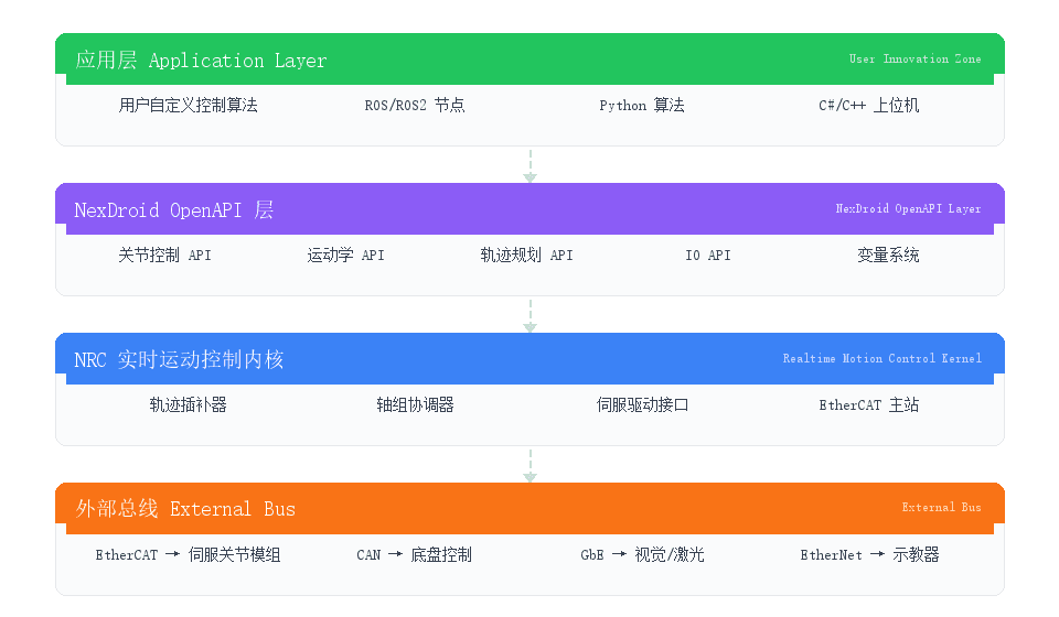
8.2 Secondary Development Interfaces (NexDroid OpenAPI)
Dual-arm control:
| Interface Category | Content | Development Language |
|---|---|---|
| Joint control | Joint position/velocity/torque command issuing | C#, Python, TCP Socket |
| Kinematics interfaces | Forward kinematics (FK) input/output access | C#, Python, TCP Socket |
| Trajectory planning | Custom trajectory generation and path issuing | C#, Python, TCP Socket |
| Admittance control | Simultaneous target position + stiffness parameter (K) + damping parameter (D) issuing for compliant interaction | C#, Python, TCP Socket |
| State feedback | Realtime reading of joint position, velocity, torque and IO states | C#, Python, TCP Socket |
| Variable system | Global/local variable read/write | C#, Python, TCP Socket |
| Servo control | Servo power on/off, alarm reset | C#, Python, TCP Socket |
| DH parameters | Online modification of robot DH parameters | Teach pendant / configuration file |
| Configuration management | Controller configuration import/export | File system |
Chassis control:
| Category | Interface | Description |
|---|---|---|
| Chassis management | Enable | Enables the chassis into a controllable state |
| E-stop | Immediately stops chassis motion | |
| Error clear | Clears chassis faults/alarm states | |
| Control mode switching | Remote control mode, navigation mode and idle mode | |
| Direct control | Velocity/angular velocity issuing | Linear and angular velocities issued via protocol for forward/reverse driving, turning and in-place rotation |
| Navigation control | Path tracking | Issues a path point sequence for tracking; forward and reverse paths supported |
| Path replacement | Replaces the current path points during operation | |
| Replanning | Triggers path replanning | |
| In-place rotation | Rotates in place to a specified heading in navigation mode | |
| Stop navigation | Aborts the current navigation task | |
| Status and configuration | Current status query | Queries realtime chassis status (position, velocity, mode, etc.) |
| Set odometry parameters | Configures odometry resolution, wheelbase and other parameters | |
| Set heading angle | Sets/corrects the chassis current heading angle |
8.3 Communication Protocols
| Protocol | Purpose | Characteristics |
|---|---|---|
| Port 7000 protocol | Core control protocol (JSON over TCP) | Query/issue joint coordinates, variables, IO; single-point and continuous trajectories |
| Custom TCP communication | Host computer ↔ controller | Server/Client modes; 9 process numbers concurrent |
| Modbus TCP/RTU | PLC/sensor integration | Flexible master/slave configuration |
| OPC-UA | Data acquisition/monitoring systems | Standardized industrial interconnection |
| EtherNet/IP | Allen-Bradley PLCs | CIP protocol support |
| FinsTCP | Omron PLCs | Command/response format |
Physical-layer communication performance: EtherCAT minimum cycle 100μs, PROFINET IRT minimum cycle 250μs, communication jitter 20μs; see Section 7.2.
8.4 ROS / ROS2 Ecosystem Support
| Module | Status | Description |
|---|---|---|
| ROS driver node | Integratable | Encapsulates ROS joint_state_publisher / trajectory_msgs via the port 7000 protocol |
| ROS2 driver node | Integratable | ROS2 nodes built on the NexDroid OpenAPI, with lifecycle management support |
| URDF model | Available on request | URDF descriptions auto-generated from DH parameters |
| TF tree | Integratable | Publishes joint transforms in realtime → builds a complete TF tree |
| MoveIt adaptation | Integratable | Exposes joint_trajectory_action / follow_joint_trajectory |
| ROS2 Control | Integratable | Interfaces with the ros2_control framework via the hardware interface layer |
Note: ROS/ROS2 drivers require secondary development integration based on the NexDroid OpenAPI; iNexBot provides interface documentation and example code.
8.5 Recommended Development Toolchain
| Tool | Purpose |
|---|---|
| Visual Studio / VS Code | C# host application development |
| Python 3.8+ | Algorithm prototyping and validation |
| ROS / ROS2 | Robot software ecosystem integration |
| Lua scripts | Rapid logic development on the teach pendant |
| TCP/UDP debugging tools | Communication protocol validation |
9. Open Dynamics Interface Specifications
9.1 Open Interfaces
| Interface | Access | Description |
|---|---|---|
| Joint angle θ | Realtime read (1ms) | Current joint angles of the 7 axes |
| Joint velocity θ̇ | Realtime read (1ms) | Current joint angular velocities of the 7 axes |
| Joint torque τ | Realtime read (1ms) | Current joint torques of the 7 axes (requires servo feedback) |
| Joint command τ_cmd | Write | Joint torque commands issued directly in torque mode |
| DH parameter table | Read/write | Standard DH / modified DH parameters, modifiable at runtime |
| Mass/inertia parameters | Read/write | Link masses, centers of mass and inertia tensors |
| Forward kinematics | Call | θ → TCP pose; built-in or user-defined |
| Inverse kinematics | Call | TCP pose → θ; built-in or user-defined |
| Jacobian matrix J(q) | Compute | Geometric/analytic Jacobian |
9.2 User-Defined Algorithm Entry Points
| Replacement Point | Replaceable Function | Interface Form |
|---|---|---|
| Joint control law | PID → sliding mode / adaptive / MPC / RL | Joint position/velocity/torque commands |
| Forward kinematics | Default algorithm → custom | θ → XYZ+RPY |
| Inverse kinematics | Default algorithm → custom | XYZ+RPY → θ |
| Trajectory planning | Trapezoidal/S-curve → custom | Path point sequence → time-parameterized trajectory |
| Dynamics feedforward | Gravity/Coriolis compensation added | τ_ff = M(q)q̈ + C(q,q̇) + G(q) |
9.3 Data Acquisition and Logging
| Function | Support |
|---|---|
| High-frequency state logging | Joint position/velocity/torque, 1ms sampling period |
| Host computer data stream | Realtime push via port 7000 (1ms level) |
| Offline logs | Local controller logs, exportable for analysis, format compatible with .csv |
10. Precision Calibration Solution — NexAutoCali Automatic Calibration System
The iNexBot wheeled humanoid robot solution integrates the self-developed NexAutoCali robot automatic calibration system, providing full-parameter precision calibration for 7-axis and 6-axis humanoid arms to ensure sub-millimeter repeat positioning accuracy in dual-arm collaborative operations.
Detailed documentation: see NexAutoCali Automatic Calibration System.
10.1 Full-Parameter Calibration
Full-parameter calibration is currently the optimal way to achieve high-fidelity alignment between the robot's theoretical model and the physical unit. It supports gear ratio calibration, zero-point calibration, link length calibration and full-parameter calibration, unlocking the equipment's own accuracy limits. After full-parameter calibration, TCP accuracy can be improved from 3mm to 0.5mm — an improvement of up to 500%.
10.2 Full Coverage of 7-Axis / 6-Axis Robots
Compatible with 7-axis collaborative arms (SRS / cross-intersecting structures) and 6-axis collaborative/industrial arms, and with the independent dual-arm configuration of wheeled humanoid robots; custom model adaptation available on request.
10.3 Fully Automated Workflow
Leveraging iNexBot's drive-control strengths, the entire workflow is automated end to end — automatic measurement point planning → automatic execution → automatic laser tracker measurement → algorithm computation → calibration result output — greatly improving ease of use and reliability.
10.4 Fast and Efficient
- Streamlined operation logic reduces training and usage difficulty
- Quick-mount design: software/hardware environment ready in 5 minutes
- Optimized calibration flow: a 50-point full-parameter calibration takes < 5 minutes typically
10.5 Highly Integrated All-in-One System
The system integrates laser tracker measurement, robot motion control, automatic calibration/measurement point planning, fully automatic calibration/test process control and algorithm computation into one package — a single software suite handles all calibration and measurement work with no additional programming.
10.6 Full-Feature Testing
- Built-in robot calibration modules: gear ratio calibration, zero-point calibration, link length calibration, full-parameter calibration
- Built-in 14-indicator robot performance test module
- Fully compliant with the national standard GB/T 12642—2013 / ISO 9283:1998
10.7 Multi-Brand Tracker Compatibility
Already compatible with the API Radian Core and other high-precision laser trackers; more brands are continuously being added.
10.8 Calibration Process Overview
Connect robot → read parameters → automatically plan measurement points → run tests automatically → data acquisition → algorithm computation → generate calibration results
11. Packaging Contents
| No. | Component | Qty | Remarks |
|---|---|---|---|
| 1 | Controller main unit | 1 | ABOX-6116, with Debian 11 / Ubuntu 20.04 |
| 2 | T30 teach pendant (optional) | 1 | Including 5m connecting cable |
| 3 | Power cable | 1 | DC 12~24V terminal connector |
| 4 | EtherCAT network cable | 2 | CAT5e or above |
| 5 | Technical documentation USB drive | 1 | Including development manuals, SDK and protocol documentation |
| 6 | NexDroid OpenAPI development kit | 1 | C# / Python example code |
12. Related Public Documentation Links
The following are public access links to related documents in the iNexBot Technology knowledge base (doc.inexbot.com):
12.1 Product Documentation
| Document | Link |
|---|---|
| iNexBot Industrial Robot Controller Datasheet | https://doc.inexbot.com/产品资料/控制系统/工业机器人控制器C1201 |
| iNexBot Industrial Robot Controller (Compact) Datasheet | https://doc.inexbot.com/产品资料/控制系统/工业机器人控制器C1102 |
| iNexBot Industrial Robot Controller (Multi-Axis) Series Datasheet | https://doc.inexbot.com/产品资料/控制系统/工业机器人控制器C2200系列 |
| T30 Teach Pendant Datasheet | https://doc.inexbot.com/产品资料/控制系统/T30示教器 |
| NexAutoCali Automatic Calibration System | https://doc.inexbot.com/产品资料/精度标定/自动标定系统NexAutoCali |
| Supported Servo Models | https://doc.inexbot.com/技术资料/支持的伺服型号 |
| Supported Robot Types | https://doc.inexbot.com/技术资料/支持的机器人类型 |
| Supported External Axis Types | https://doc.inexbot.com/技术资料/支持的外部轴类型 |
12.2 Operation Manuals
| Document | Link |
|---|---|
| Motion Control Commands | https://doc.inexbot.com/操作手册/24.03版本/运动控制类指令 |
| Robot DH Parameter Description | https://doc.inexbot.com/操作手册/24.03版本/机器人DH参数说明 |
| Multi-Robot and Dual-Robot Collaboration | https://doc.inexbot.com/操作手册/24.03版本/多机与双机协作 |
| New Dual-Robot Features | https://doc.inexbot.com/操作手册/24.03版本/新双机功能 |
| Multi-Robot Coordination Commands | https://doc.inexbot.com/操作手册/24.03版本/多机协调类指令 |
| Interference Zones | https://doc.inexbot.com/操作手册/24.03版本/干涉区 |
| External Axis User Manual | https://doc.inexbot.com/操作手册/24.03版本/外部轴使用手册 |
| Independent Axis Control | https://doc.inexbot.com/操作手册/24.03版本/独立轴控制 |
| Servo Response Time | https://doc.inexbot.com/操作手册/24.03版本/伺服响应时间 |
| System Function Debugging Manual | https://doc.inexbot.com/操作手册/24.03版本/系统功能调试手册 |
| Target Configuration Calculation Commands | https://doc.inexbot.com/操作手册/24.03版本/计算目标形态指令 |
| Tool Frame Calibration Manual | https://doc.inexbot.com/操作手册/24.03版本/工具手标定手册 |
| User Coordinate Calibration Manual | https://doc.inexbot.com/操作手册/24.03版本/用户坐标标定手册 |
12.3 Secondary Development and Communication Protocols
| Document | Link |
|---|---|
| Port 7000 User Manual | https://doc.inexbot.com/操作手册/24.03版本/7000端口 |
| TCP Communication Function Manual | https://doc.inexbot.com/操作手册/24.03版本/TCP通讯功能手册 |
| Modbus Function User Manual | https://doc.inexbot.com/操作手册/24.03版本/Modbus功能使用手册 |
| OPC-UA Parameters | https://doc.inexbot.com/操作手册/24.03版本/OPC-UA参数 |
| EIP Function Operating Instructions | https://doc.inexbot.com/操作手册/24.03版本/EIP功能操作说明 |
| FINSTCP User Manual | https://doc.inexbot.com/操作手册/24.03版本/FINSTCP使用手册 |
| Lua Tutorial | https://doc.inexbot.com/操作手册/24.03版本/Lua教程 |
| PC Simulation Software Tutorial | https://doc.inexbot.com/操作手册/24.03版本/PC支持仿真软件使用教程 |
| Communication Protocol & Address Codes | https://doc.inexbot.com/技术资料/通讯协议&地址码 |
12.4 Process Applications
| Document | Link |
|---|---|
| Vision Process | https://doc.inexbot.com/操作手册/24.03版本/视觉工艺 |
| Conveyor Tracking Process Manual | https://doc.inexbot.com/操作手册/24.03版本/传送带跟踪工艺手册 |
| Welding Process | https://doc.inexbot.com/操作手册/24.03版本/焊接工艺 |
| Palletizing Process | https://doc.inexbot.com/操作手册/24.03版本/码垛工艺 |
| Laser Cutting Process | https://doc.inexbot.com/操作手册/24.03版本/激光切割工艺 |
Disclaimer
The ROS/ROS2 support, open dynamics interfaces and other features listed in this datasheet are based on the NexDroid OpenAPI platform; some integration work must be completed by the user following the provided development documentation and example code. The actual level of feature implementation is subject to the technical annex of the contract. RK3588 platform parameters are reference values; actual performance may vary with system configuration and operating environment.
- iNexBot Technology Knowledge Base: https://doc.inexbot.com
- Developer Center: https://ones.inexbot.com
- Technical support: please contact your local iNexBot Technology sales representative or an authorized system integrator