Industry Introduction
Screw fastening is a core process in 3C electronics, automotive electronics and home appliance assembly. Robots equipped with electric screwdrivers perform automatic fastening, and precise alignment between the bit and the screw hole is the prerequisite for successful fastening. After a bit change, a collision or normal wear, tiny TCP offsets (0.1~0.5mm) can cause stripped threads, poorly seated screws and scrapped products.
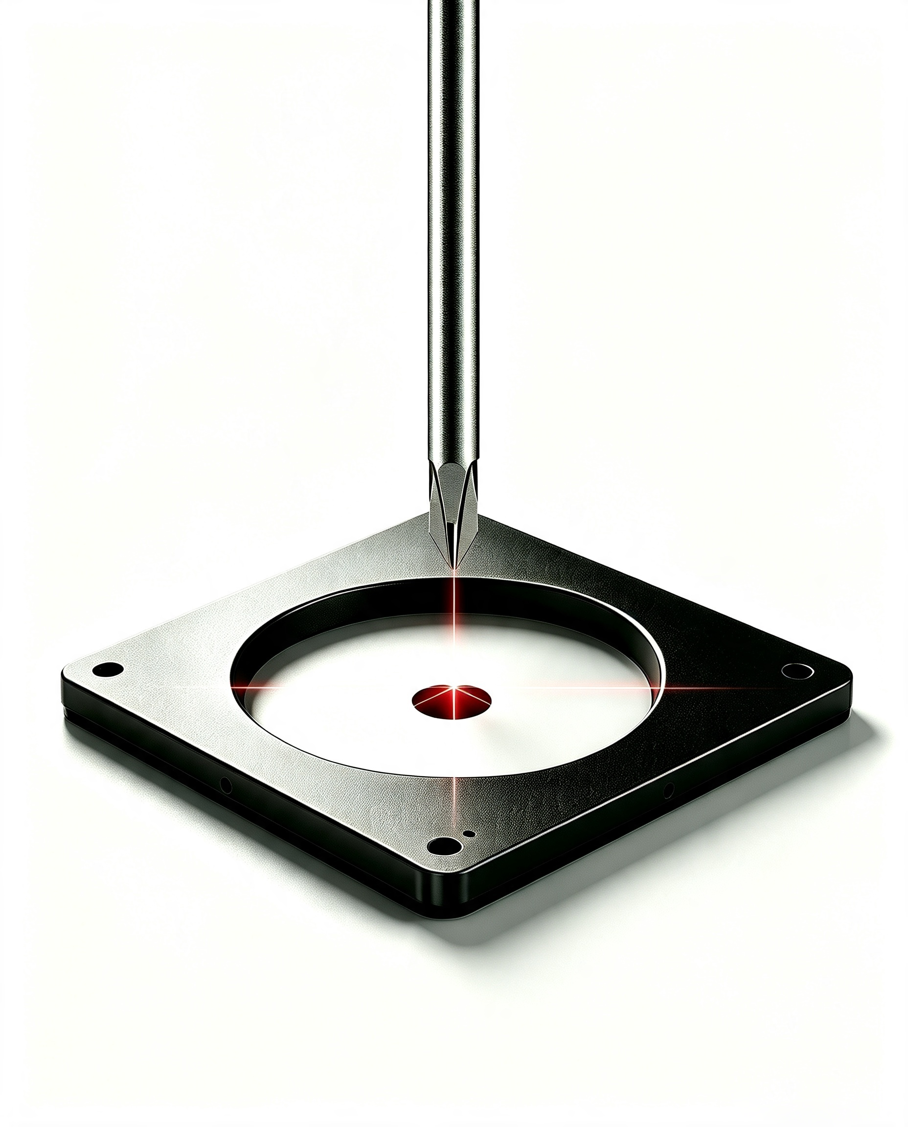
Industry Pain Points
- Invisible TCP offset: a bit offset of 0.1~0.5mm cannot be seen by the naked eye, yet it is enough to cause thread stripping or fastening failure
- Delayed defect detection: defects caused by TCP offset are often only discovered at quality inspection, by which time a whole batch is already defective
- Tedious traditional calibration: manual alignment with dial indicators or teach needles is time-consuming, and accuracy depends on feel
- Inconsistent multi-station results: calibration results vary between stations, causing fluctuation in final assembly accuracy
- Long changeover times: recalibration after bit changes consumes a large share of changeover time
Our Advantages
The iNexBot TCP automatic calibration system uses a cross-laser sensor + five-point automatic calibration algorithm, tailored for fastening applications:
| Metric | Manual Calibration | Automatic Calibration | Improvement |
|---|---|---|---|
| Calibration time | 10~20 min | 5~7 min | ↓60%+ |
| Calibration accuracy | ±0.1mm | ±0.02mm | ↑5× |
| Consistency | Experience-dependent, highly variable | Fully automatic and standardized, highly consistent | — |
| Probing method | Contact (dial indicator/teach needle) | Non-contact laser (zero wear) | — |
| Data traceability | None | Automatic MES upload, SPC trend analysis | — |
Our Solution
One-touch start from the teach pendant; the system automatically completes: trajectory generation → motion acquisition → tool calculation → write to tool frame.
The operator teaches 5 calibration points on the teach pendant the first time; every subsequent calibration (after bit changes or collisions) is triggered with one touch. Calibration data is automatically uploaded to the MES, generating a TCP drift trend curve that supports SPC monitoring and predictive maintenance. No additional host computer is needed — natively integrated into the teach pendant.
After the initial calibration, the calibration program can be reused, and the calibration process can be launched automatically at set intervals for the bits, reducing product scrap caused by drift.
Hardware Used
| Hardware | Description |
|---|---|
| Cross-laser sensor | Laser beam diameter 0.3~1.0mm; 120mm and 220mm beam-distance versions available; compatible with all common bit types |
| Robot controller | Compatible with multiple of our controller models |
| Host computer | Self-developed intelligent fastening system |
Robot Types
Compatible with the robots commonly used in fastening applications: SCARA, 6-axis industrial robots and collaborative robots.
Communication Methods
| Method | Scenario |
|---|---|
| EtherCAT | Controller ↔ sensor direct connection |
| PROFINET / EtherNet/IP | PLC-triggered calibration |
| Modbus TCP | MES data upload |
| Hardwired I/O | Calibration start/complete/alarm signals |
FAQ
Q1: What accuracy can screw fastening TCP calibration achieve?
Calibration accuracy is ±0.02mm, and a verification closed loop ensures every written deviation is within tolerance — far beyond the manual ±0.1mm level.
Q2: Are there requirements for bit specifications?
The cross-laser beam diameter is 0.3~1.0mm, compatible with common fastening bit sizes; non-contact probing means no wear.
Q3: What is needed for first deployment? Does every subsequent calibration require re-teaching?
Teach 5 points on the teach pendant the first time and the system saves them. Subsequent calibrations are triggered with one touch, taking 5~7 minutes in total.
Q4: Is an additional host computer required?
No. The system is integrated directly into the teach pendant; enabled by a software upgrade, at zero hardware cost.
Q5: Fastening stations have limited space — will it fit?
Yes. The cross-laser sensor is available in two sizes and mounts in a corner of the station table, taking up no fastening workspace.
Q6: Does calibration require stopping the line?
No. Calibration runs automatically when bits are changed or before a shift starts, without affecting normal operation.
Q7: Can calibration data be integrated with the MES?
Yes. The timestamp, offset and verification deviation of each calibration are automatically uploaded to the MES, generating a TCP drift trend curve. When the offset shows a steadily increasing trend, SPC provides early warning of bit wear or module loosening.
Q8: What happens if calibration fails?
An automatic re-verification is performed; if the deviation exceeds the threshold, an alarm is triggered, the calibration result is not written, and the device keeps the last valid TCP value. The MES is notified at the same time so engineers can investigate.
Q9: Does the sensor need periodic calibration?
No. The optical path is fixed inside the sensor and remains valid for life after factory calibration. Just keep the lens clean.
Q10: How is after-sales and technical support guaranteed?
Remote debugging + on-site support.