Weld Quality
Weld quality is related not only to smooth wire feeding but also to many external conditions and the welding process. The premise for ensuring weld quality is a stable overall environment and the correct application of the process.
01 Setting Up the External Environment
The external environment for welding has very high requirements:
- Smooth wire feeding.
- The welding worktable must be reliably grounded.
- Shielding gas flow control: for thin plates, generally 12-15 L/min;
- For thick plates, generally 15-20 L/min.
02 Welding Process
The welding process includes welding parameter settings and practical welding techniques.
A. Welding Parameter Settings
1. Welding Voltage and Welding Current
Welding voltage is the arc voltage, which provides welding energy and weld quality; welding current is the current flowing through the welding circuit during welding, resulting from the balance between wire feed speed and melting rate.
Welding voltage affects the width of the weld pool; welding current affects the depth of the weld pool. As a general rule: the higher the welding voltage, the wider the weld pool; the higher the welding current, the deeper the weld pool — and vice versa.
Most welding machines come with an expert database. When using synergic (one-knob) welding, the expert database is effectively enabled; fine-tuning on top of it usually gives good results.
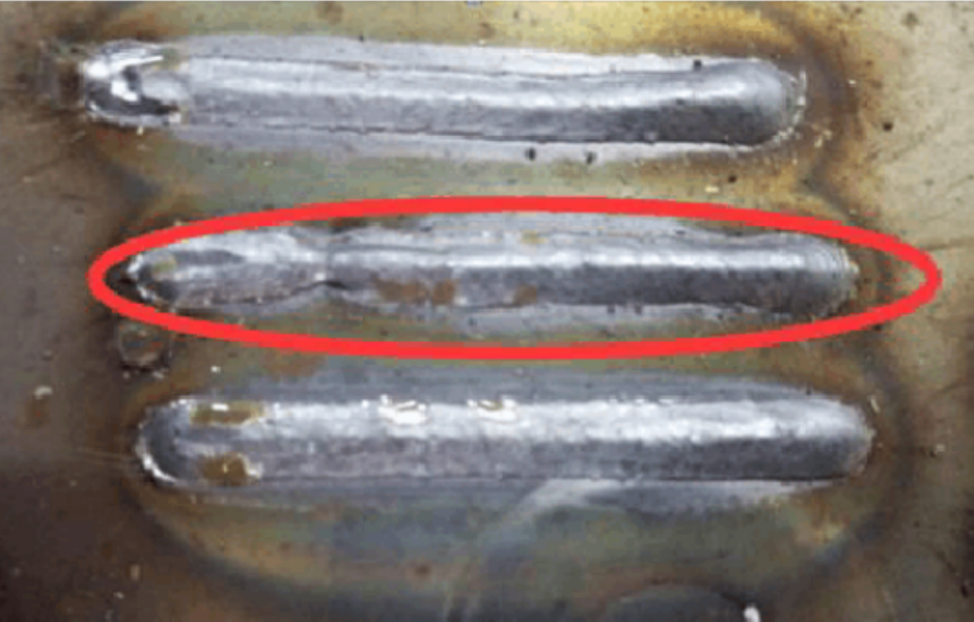
In the figure above, the middle weld bead is relatively narrow; by ensuring smooth wire feeding and appropriately increasing the voltage, better results can be achieved (like the bottom weld bead).
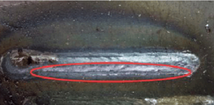
Welding voltage must not be set too high, otherwise undercut will occur, as shown below:
Generally, the arc starting current and voltage are higher than the welding current and voltage (about 120%-140% of the welding voltage), though they can also be lower than the actual welding current/voltage, depending on the actual situation.
When all other parameters are kept constant, increasing the welding current (wire feed speed) will cause the following changes:
① Increased penetration and width of the weld.
② Higher deposition rate.
③ Larger weld bead size.
2. Pre-flow and Post-flow Gas
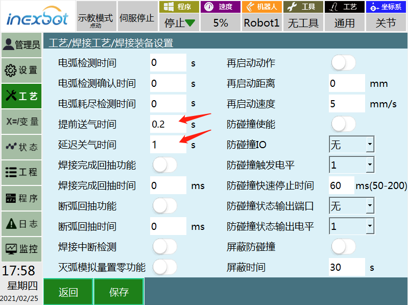
Pre-flow time is generally set short, around 0.2 s; post-flow time is generally set to about 1 s to protect the pool that has not yet cooled. Specific settings should be determined according to the on-site welding requirements.
3. Welding Speed
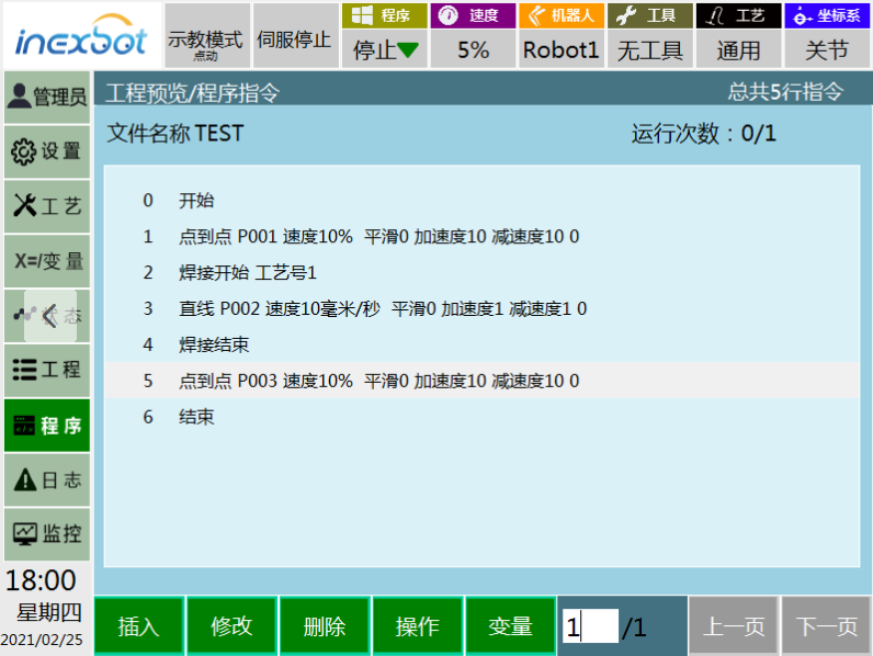
Welding speed is the linear speed at which the arc moves along the welding joint.
With other conditions unchanged, a medium welding speed gives maximum penetration. When welding speed decreases, the amount of deposited metal per unit length of weld increases; at very slow speeds, the arc impinges on the pool rather than the base metal, reducing effective penetration and widening the bead.
4. Wire Stick-Out
Wire stick-out is the distance from the contact tip to the end of the wire. Keeping the stick-out constant during welding is one of the important factors for stable welding.
Generally, the stick-out is 10 to 15 times the wire diameter. Too long a stick-out results in poor gas shielding, porosity, shallower penetration and poor bead appearance. Too short a stick-out can lead to nozzle blockage by spatter, the wire sticking to the contact tip, and deeper penetration.
5. Arc Start Confirmation Time
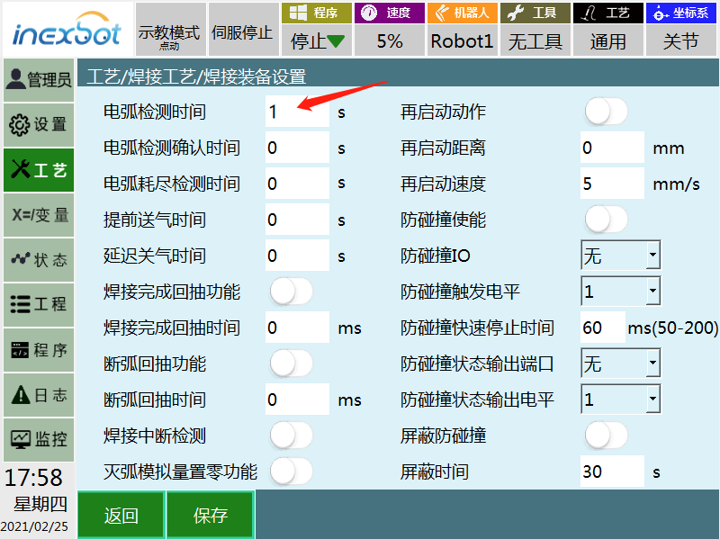
The arc start confirmation time parameter continuously checks for the returning arc start signal within the set time. If the arc does not start within the time, the system alarms, the robot stops, and arc starting fails.
Generally, the larger this parameter, the easier the arc starts. However, if it is set too large, the wire may extend too far when the arc start signal doesn't come, causing other accidents. It is generally recommended to set it to 1-4 s.
6. Slow Wire Feed Speed
Slow wire feed speed is the wire feeding speed as the wire extends from the start of arc striking to the surface of the base metal. This parameter takes effect when set on the welding machine side: from the arc start signal being sent to the wire contacting the base metal, and then successful arc starting.
Therefore, the slow wire feed speed and the distance from the wire to the base metal at arc start directly determine how fast the arc starts. The default value is generally 1.4 m/min to 3.6 m/min.
7. Burnback Time
Burnback time refers to the period after welding ends during which the wire continues to burn at the end point, controlling the stick-out and thus helping determine the next arc start time. When properly controlled, burnback also provides functions such as balling the wire end and preventing wire sticking. The recommended setting is 0.06 s to 0.08 s.
B. Practical Welding Techniques
Besides setting welding parameters correctly, there are many practical techniques for controlling weld results during welding.
The orientation of the torch relative to the welding joint affects the bead shape and penetration — even more than arc voltage or welding speed. These include the angle between the wire axis and the welding direction (travel angle) and the angle between the wire axis and the adjacent work surface (work angle).
When the wire points opposite to the welding direction, it is called the backhand (dragging) technique; when the wire points in the welding direction, it is called the forehand (pushing) technique.
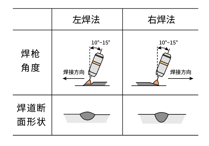
When other welding conditions remain unchanged, changing from a vertical wire to the forehand technique reduces penetration and makes the bead wider and flatter.
When using the backhand technique in the flat position, the arc force blows the pool backward, so the arc acts directly on the base metal, producing greater penetration, a narrow and convex bead, a more stable arc, and less spatter.
For various welding positions, the wire angle is mostly chosen in the range of 10°-15°, which provides good control and protection of the weld pool.
In robotic welding, the forehand technique is mostly used. It provides good cleaning action: under the arc force, the molten metal is pushed forward, promoting wetting of the base metal and reducing oxidation.
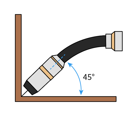
When welding horizontal fillet welds, the wire axis should be placed at a 45° angle (work angle) to the horizontal plate. When welding horizontal fillet welds on thin plates, point the wire at the weld; when welding thick plates, to keep the weld symmetrical, the heat dissipation of the vertical side and the horizontal side must be considered — the upper plate dissipates heat poorly and the lower plate dissipates heat well, so the arc should point at the lower plate. As shown in the figure below: