What Is a Tool Coordinate System?
Flange center: the origin of the default tool coordinate system. From the flange center toward the flange locating hole is the +X direction; perpendicular to the flange, pointing outward, is the +Z direction; the Y direction is then determined by the right-hand rule. Every new tool coordinate system is derived by transforming the default tool coordinate system.
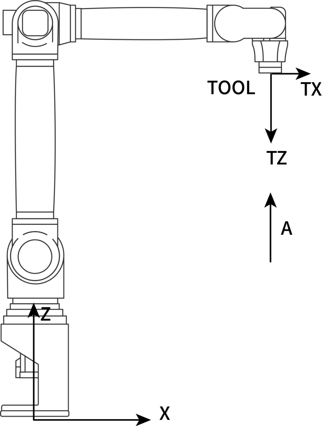
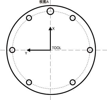
TCP: Tool Center Point, i.e., the center point of the tool.
Robot path and speed: refers to the path and speed of the TCP point.
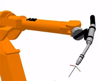
The TCP is usually set at the center of the gripper, the tip of the welding wire, the front end of the fixed arm of a spot-welding gun, and so on.
To describe the position of an object in space, a coordinate system must be fixed to the object, and the pose of that coordinate system (the origin position and the orientation of the three coordinate axes) must be determined — that is, 7 DOFs are needed to fully describe the pose of the rigid body [1]. For industrial robots, a tool must be mounted on the end flange to perform work. To determine the pose of this tool, a tool coordinate system TCS (Tool Coordinate System) is attached to it, and the origin of the TCS is the TCP (Tool Center Point). When programming robot paths, the pose of the TCS relative to other coordinate systems needs to be recorded in the program for execution.
Industrial robots generally come with a predefined TCP: the XY plane of the TCP is bound to the flange plane of the robot's sixth axis, and the origin of the TCP coincides with the flange center. Clearly, the TCP is at the flange center. ABB robots call this TCP tool0, and REIS robots call it _tnull. Although the default TCP can be used directly, in actual applications such as welding, users typically define the TCP at the tip of the welding wire (in fact, the pose of the welding gun's tool coordinate system relative to the tool0 coordinate system). The position recorded in the program is then the position of the wire tip, and the recorded orientation is the orientation of the gun rotating around the wire tip.
Think About It
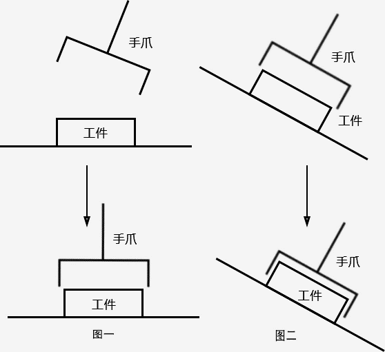
The tool coordinate system is an object of study in motion, but what role does it actually play during commissioning? Think about how the gripper orientation and position in Figures 1 and 2 are adjusted.
Inference: based on the above, two inferences can be drawn:
Inference 1: If the gripper in Figure 1 has a rotation point, the gripper can be adjusted by simply rotating it around that point.
Inference 2: If the gripper in Figure 2 has a forward direction, it can simply be moved along that direction.
Conclusion: the purposes of establishing a tool coordinate system:
-
Define the tool's TCP point (i.e., the tool center point), making it convenient to adjust the tool state.
-
Determine the tool feed direction, making it convenient to adjust the tool position.
Characteristics of the Tool Coordinate System
A new tool coordinate system is derived from the default tool coordinate system. Its position and orientation always maintain an absolute positional and orientational relationship with the flange, but they keep changing in space.
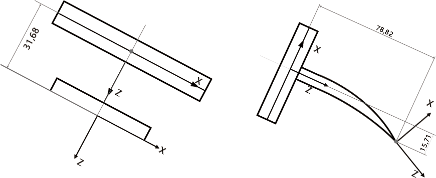
When tool parameters are required: tool calibration is needed when orientation rotations around X, Y, and Z are required.
When tool parameters are not required: if the robot only rotates its orientation about the Z axis and the tool tip lies on the extension of the centerline of the robot's 6th-axis flange, tool parameters can be omitted.
What Is Tool Calibration?
Tool calibration aligns the tool tip with a fixed point in space and calculates the tool's dimensions and orientation from a set of sampled points.
The following conditions must be met for tool calibration:
- Robot type: six-axis articulated robot or six-axis collaborative robot
- The tool tip must have a feature that can be aligned with the calibration cone: a pointed tool
- The robot's body parameters must be accurate
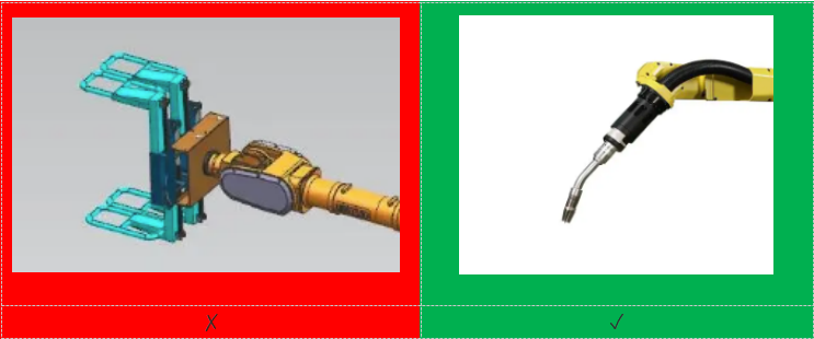
Note: if the tool has no point that can be aligned with the calibration cone, a specific pointed object can be gripped with the gripper and used for calibration; the calibration accuracy depends on how the pointed object is placed.
How to Choose a Calibration Method
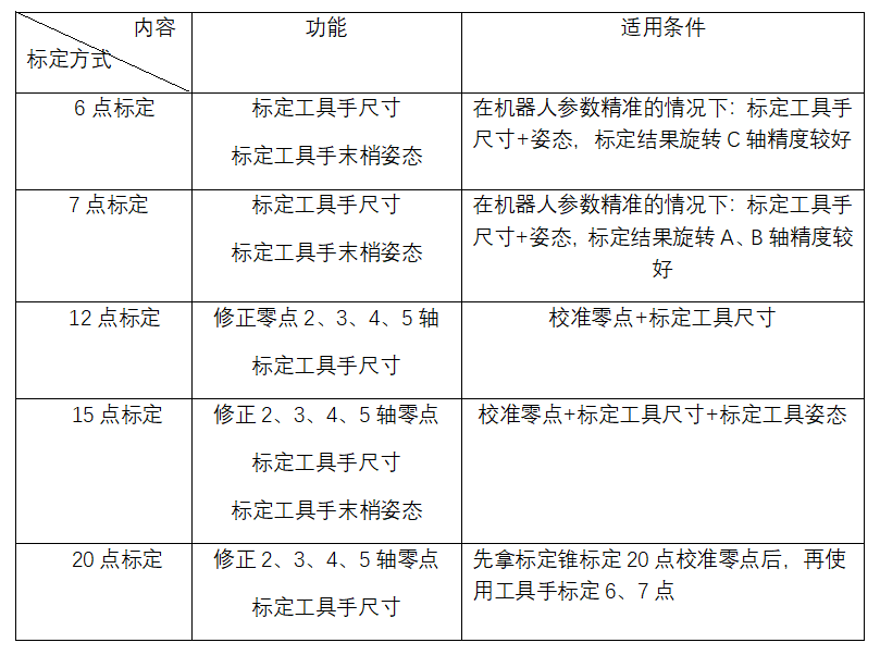
The characteristics of the calibration methods are as follows:
Scenario 1: The Robot Has Undergone Laser Calibration and Uses a Welding Gun
Recommended: use 6-point tool calibration, then verify the calibration results after calibration.
Scenario 2: The Robot Has Not Undergone Laser Calibration and Uses a Welding Gun
Recommended: use 12-point tool calibration, then verify the calibration results after calibration.
Scenario 3: Calibrating a Palletizing Gripper
Recommended: first choice is to enter the tool dimensions directly; if the dimensions are unknown, use 6-point calibration.
- Prepare a pointed object that can be gripped, and place it as far into the gripper as possible
- Use 6-point tool calibration
- After calibration, verify the calibration results.
Scenario 4: The Robot Has Lost Its Zero Point, and the Zero Position Calibrated with Alignment Holes Has Deviation
Recommended:
- Prepare a calibration tool whose tip lies as close as possible to the extension of the 6th-axis flange centerline, with small tool dimensions
- Use 20-point calibration to correct the zero point
- After the 20-point calibration, switch to the tool actually used and perform 6-point calibration
- After calibration, verify the calibration results.
Scenario 5: After 6-Point Calibration, A- and B-Axis Rotation Errors Are Still Too Large for the Application
Recommended: switch to 7-point calibration