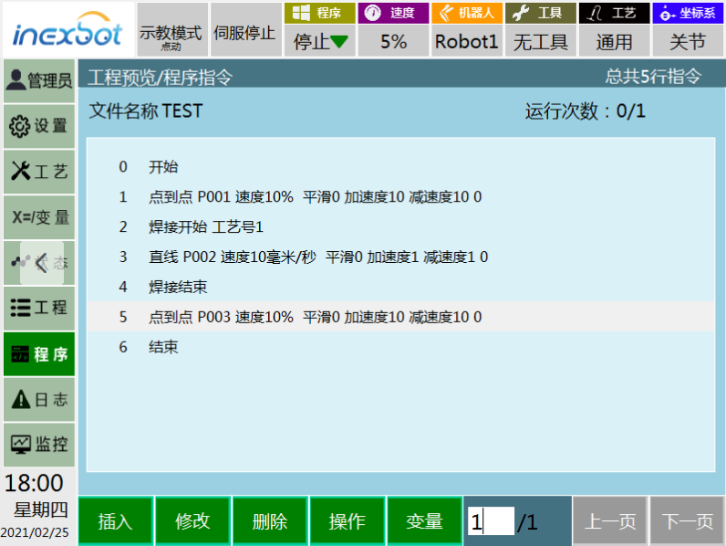
Welding Quality
The welding quality is not only related to smooth wire feeding but also to various external conditions and welding processes. Ensuring welding quality requires a stable environment and correct application of the welding process.
01 Establishment of External Environment
Welding has high requirements for the external environment:
- Smooth wire feeding
- Reliable grounding of the welding workstation
- Control of shielding gas flow rate: Generally, for welding thin plates, it should be controlled at 12-15 L/min; for welding thick plates, it should be controlled at 15-20 L/min
02 Welding Process
The welding process involves the settings of welding parameters and actual welding skills.
A. Setting Welding Parameters
1. Welding voltage and welding current
Welding voltage, also known as arc voltage, provides welding energy and influences welding quality. Welding current refers to the current flowing through the welding circuit during welding and is the result of balancing wire feeding speed and melting speed.
Welding voltage affects the width of the weld pool, while welding current affects the depth of the weld pool. Generally, the following rules can be followed for adjustment: higher welding voltage results in a wider weld pool, and higher welding current results in a deeper weld pool, and vice versa.
Most welding machines have built-in expert libraries, which can be fine-tuned for better results when using unified welding.
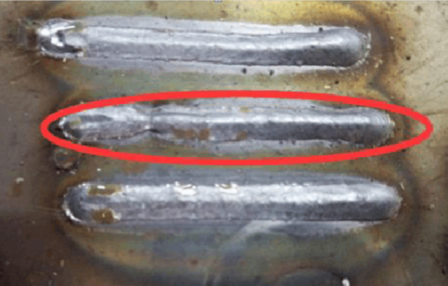
The narrow weld seam in the middle of the photo can achieve better results by ensuring smooth wire feeding and slightly increasing the voltage (as shown in the bottom weld seam).
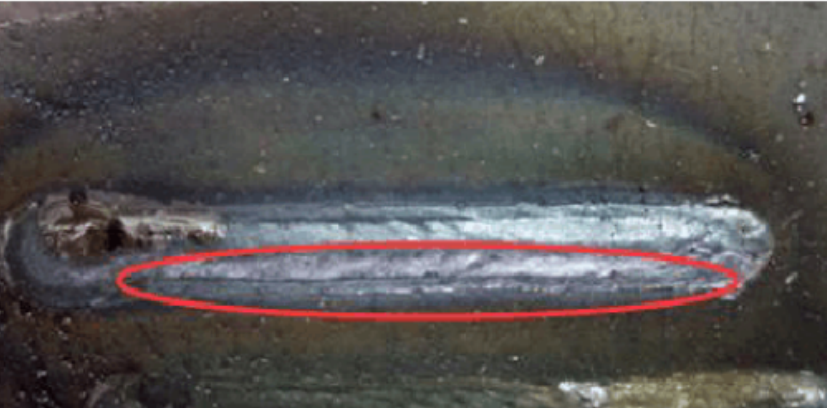
Setting the welding voltage too high can cause undercutting, as shown in the image below:
In general, the arc ignition current/voltage is higher than the welding current/voltage (around 120%-140% of the welding voltage), but it can also be lower depending on the specific welding requirements and conditions.
When all other parameters are kept constant, increasing the welding current (wire feeding speed) will result in the following changes:
① Increased depth and width of the weld pool
② Increased deposition rate
③ Increased size of the weld bead
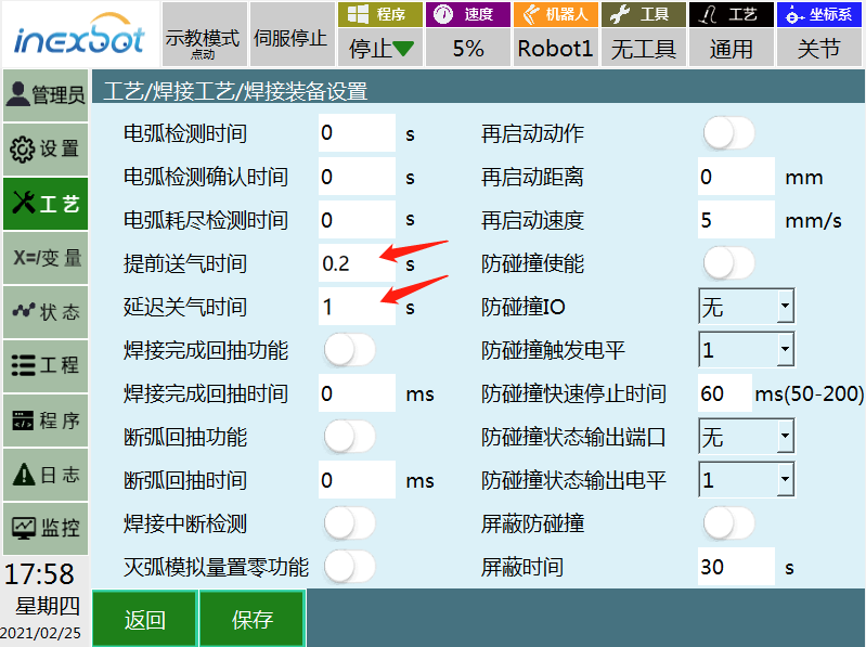
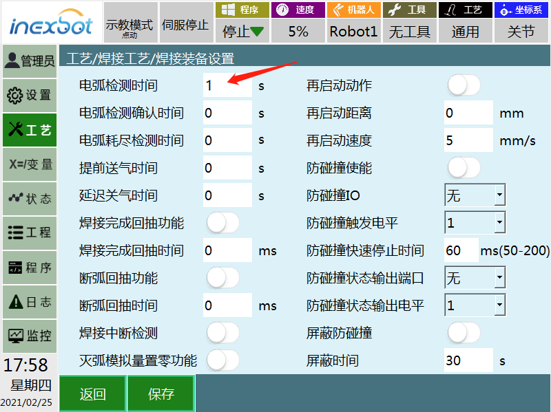
2. Gas pre-flow time and gas post-flow
The gas pre-flow time is usually set to a short duration of around 0.2 seconds, while the gas post-flow time is commonly set to around 1 second. These parameters are used to protect the still-hot weld pool. The exact settings depend on the welding requirements of the specific application.
3. Welding speed
Welding speed refers to the linear speed at which the arc travels along the weld joint.
When other conditions remain unchanged, a moderate welding speed results in the maximum penetration depth. As the welding speed decreases, the amount of deposited metal per unit length increases. At very slow welding speeds, the welding arc impinges on the weld pool rather than the base metal, resulting in reduced effective penetration depth and an increased width of the weld bead.
4. Wire stick-out
Wire stick-out is the distance between the contact tip and the end of the welding wire. Maintaining a consistent wire stick-out length is one of the key factors for ensuring stable welding.
In general, the stick-out length is around 10 to 15 times the diameter of the welding wire. If the stick-out length is too long, it can result in poor gas shielding, leading to porosity, reduced penetration depth, and poor formation of the weld.
On the other hand, if the stick-out length is too short, it can cause the nozzle to get easily blocked by spatter, the welding wire to stick to the contact tip, and increased penetration depth.
5. Arc ignition confirmation time
The "Arc ignition confirmation time" parameter is used to continuously detect the arc ignition signal within a set time. If the arc is not ignited within this time, the system will trigger an alarm, stop the robot, and indicate a failed arc ignition.
6. Slow wire feed speed
Slow wire feed speed refers to the feeding speed of the wire during the process of extending it to the surface of the base material after arc ignition. This parameter needs to be set and effective on the welding machine side. The arc ignition signal is emitted, and the wire contacts the base material to successfully ignite the arc.
Therefore, the slow wire feed speed and the length of the wire from the base material at the start of the arc ignition directly affect the speed of arc ignition. The default values are generally set between 1.4m/min to 3.6m/min.
7. Burn-back Time
Burn-back time refers to the duration during which the welding wire continues to burn at the end point after the welding process has ended. It helps to control the wire stick-out length and has a certain influence on the next arc ignition time. When properly controlled, burn-back time can also facilitate wire end ball removal and prevent wire sticking. The recommended setting range is 0.06s to 0.08s.
B. Welding Practical Techniques
In addition to setting welding parameters appropriately, there are many practical techniques to control the welding effect.
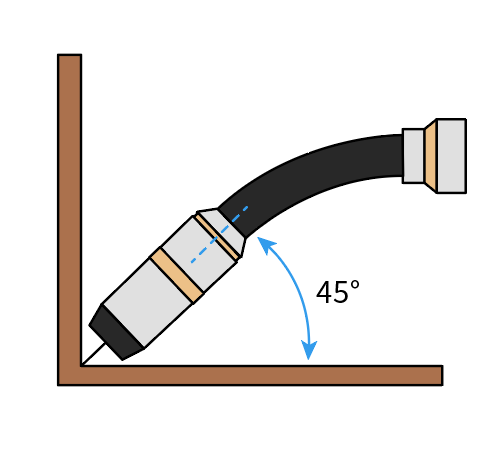
The direction of the welding gun relative to the welding joint affects the shape and penetration depth of the weld bead. This impact is more significant than the influence of arc voltage or welding speed. Two key angles are considered: the travel angle, which is the angle between the wire axis and the welding direction, and the work angle, which is the angle between the wire axis and the adjacent work surface.
When the wire points in the opposite direction of welding, it is called right-hand welding. When the wire points in the direction of welding, it is called left-hand welding.
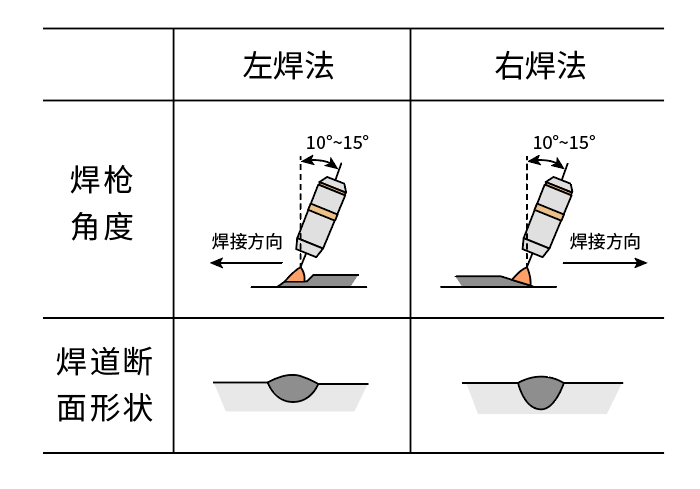
When other welding conditions remain unchanged and the wire changes from a vertical position to left-hand welding, the penetration depth decreases, and the weld bead becomes wider and flatter.
In the flat welding position, when right-hand welding is used, the weld pool is blown backward by the arc force. As a result, the arc directly acts on the base metal, leading to a greater penetration depth. The weld bead becomes narrower and more convex, and the arc stability and spatter decrease.
For various welding positions, the wire angle is mostly chosen within the range of 10° to 15°. This allows for good control and protection of the weld pool.
Left-hand welding is often used in robot welding, as it provides good cleaning action. The weld pool, under the influence of the arc force, is blown forward, promoting wetting of the base metal and reducing oxidation.