As welding robots become more common, process requirements are getting higher, and people pay particular attention to weld appearance — some workpieces require a fish-scale pattern at the weld, which requires the welding machine to have a pulse function. The welding process of the iNexBot robot control system is also continuously innovating in practical scenarios. Below we introduce the fish-scale welding process in the iNexBot welding suite.
Types of Fish-Scale Welding
Setting Up Fish-Scale Spot Welding
In the program — Insert — Welding Control — Fish-Scale Welding, when the type is set to fish-scale spot welding, the spot weld time T and the travel distance L2 must be set.
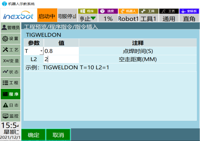
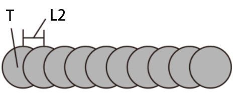
When fish-scale spot welding is used, the robot does not move during welding — it stops at the set point to weld. The spot weld time T is the welding time at each set point, and the travel distance L2 is the distance between points.
Setting Up Fish-Scale Section Welding:
In the program — Insert — Welding Control — Fish-Scale Welding, when the type is set to fish-scale section welding, the welding distance L1 and the travel distance L2 must be set.
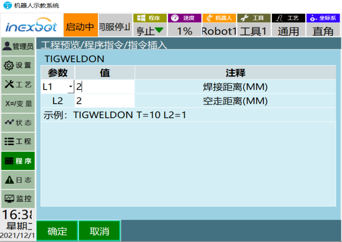
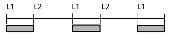
When fish-scale section welding is used, the welding robot moves and welds during motion. The welding section is the welding distance L1, and the travel distance L2 is the distance between points.
Programming
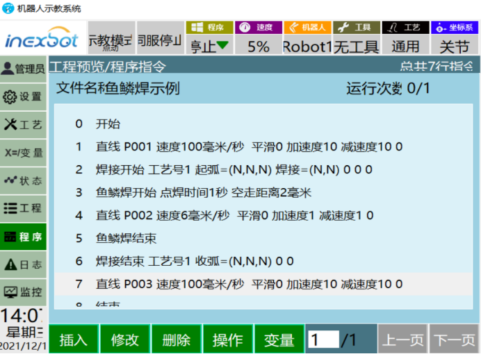
Program Example
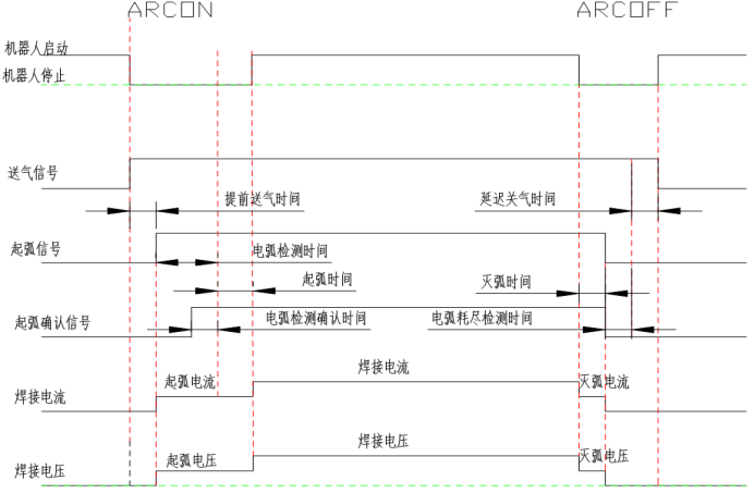
Welding Sequence
Using the program example: first the arc start section, then welding time 1 s, then the arc end section, finally travel 2 mm; loop the previous 4 steps until the welding end point is reached.
Methods for Optimizing Fish-Scale Welding
Welding External Environment Settings
① Smooth wire feeding. ② Reliable grounding of the welding worktable. ③ Shielding gas flow control: thin plates generally 12-15 L/min; thick plates generally 15-20 L/min.
Welding Parameter Settings
Welding Current and Voltage Settings
Welding voltage is the arc voltage, which provides welding energy and weld quality; welding current is the current flowing through the welding circuit during welding, resulting from the balance between wire feed speed and melting rate. Welding voltage affects the width of the weld pool; welding current affects the depth of the weld pool. As a general rule: the higher the welding voltage, the wider the weld pool; the higher the welding current, the deeper the weld pool — and vice versa. Most welding machines come with an expert database; when using synergic (one-knob) welding, the expert database is effectively enabled, and fine-tuning on top of it usually gives good results.
Wire Stick-Out
Wire stick-out is the distance from the contact tip to the end of the wire. Keeping the stick-out constant during welding is one of the important factors for stable welding; generally, the stick-out is 10 to 15 times the wire diameter.
Welding Speed
Welding speed is the linear speed at which the arc moves along the welding joint. With other conditions unchanged, a medium welding speed gives maximum penetration.
Example Cases
Case 1
| No. | Material | Plate thickness (mm) | Wire diameter (mm) | Welding current (A) | Welding voltage (V) |
|---|---|---|---|---|---|
| 1 | Carbon steel | 3.2 | 1.2 | 130 | 20 |
| 2 | Carbon steel | 3.2 | 1.2 | 130 | 22 |
| 3 | Carbon steel | 3.2 | 1.2 | 130 | 20 |
- Weld 1 uses a welding current/voltage of 130 A, 20 V; the overall effect is average, but the three-dimensional feel is weak.

- Weld 2 uses a welding current/voltage of 130 A, 22 V; the weld bead is flatter, with signs of undercut at the edges, caused by excessive voltage.

- Weld 3 uses a welding current/voltage of 130 A, 20 V; compared with Figure 1, the wire stick-out speed was doubled and the travel distance L2 between spots was reduced by 0.5 mm; the weld bead is more uniform and the overall effect is better.

Case 2
| No. | Material | Plate thickness (mm) | Wire diameter (mm) | Welding current (A) | Welding voltage (V) |
|---|---|---|---|---|---|
| 1 | Carbon steel | 2.3 | 1.0 | 120 | 18 |
| 2 | Carbon steel | 2.3 | 1.0 | 110 | 18 |
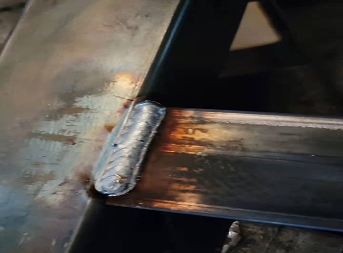
- The weld in the figure below uses a welding current/voltage of 120 A, 18 V, a spot weld time of 0.41 s and a travel distance of 2 mm; the bead has many protrusions — the spot weld time is too long, and later grinding will be needed to flatten it.
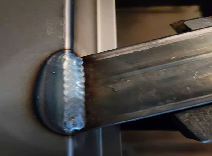
- The weld in the figure below uses a welding current/voltage of 110 A, 18 V, a spot weld time of 0.3 s and a travel distance of 1.2 mm; after adjusting the current and the spot weld time, the bead is more compact, with no protrusions on the surface, meeting the overall requirements.
Summary
When using fish-scale welding, pay attention to adjusting the spot weld dwell time T and the travel distance L2. With the same welding parameters, the longer the spot weld dwell time, the fuller the fish scales; the longer the travel distance, the wider the spacing, and the smaller the overlap between adjacent scales. The dwell time, travel distance and welding speed together complete the pulsed welding of the entire fish-scale pattern, achieving the fish-scale appearance.