Laser Positioning/Tracking
Laser positioning and laser tracking technologies enable robots to identify weld seams using lasers and perform welding based on manually taught welding trajectories. It's like giving the robot a pair of "eyes".
During the manual teaching process of welding, the weld seam is susceptible to deformation, gap variation, and assembly errors, leading to significant deviations in the weld seam during the welding process. In order to improve the welding quality, the welding robot needs to be controlled in real time to correct the weld seam deviation.
Principle of Laser Weld Seam Inspection
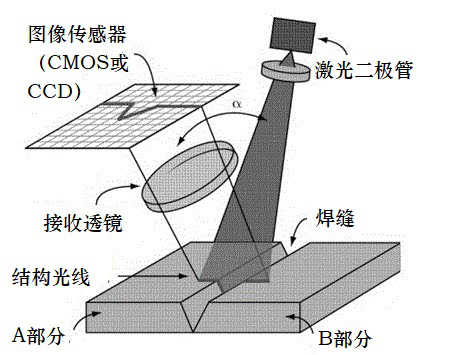
A laser diode emits laser beams onto the surface of the workpiece. The laser beam is reflected on the surface and forms an image on a CCD or CMOS sensor. The image data is then communicated to a controller, which processes the image to determine the position of the weld seam. This information is used to control a robot for tracking or positioning.
Actually, most of the welding robots in the current market use the "teach and playback" mode for operation, with a few utilizing trajectory planning. In other words, regardless of the type of product, welding processes are carried out based on design data. First, a predetermined theoretical program is written, and then the welding operation takes place. For large batches of identical workpieces, laser positioning or tracking technology is often used to determine the welding trajectory. Due to potential errors in mass production, laser correction is necessary to ensure a welding qualification rate of over 90%.
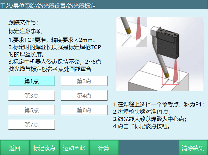
Laser Calibration
The calibration process includes diagrams and written instructions, and it is relatively simple and easy to get started as long as you can understand the weld seam recognition image on the PC.
Laser Positioning
Please refer to the following video.
You can also refer to the demo video of iNexBot.
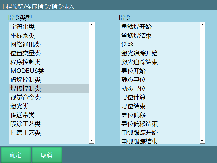
Specialized laser positioning instructions
iNexBot laser positioning primarily consists of static positioning, dynamic positioning, position offset, and the crucial positioning calculation. For users, programming is relatively simple and does not require complex logic. Additionally, a single algorithm can be applied to an entire assembly line of identical workpieces.
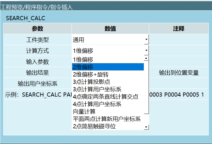
Laser positioning algorithm
Laser positioning can be used on a production line to perform positioning correction or determine the start and end points of welding for identical workpieces. However, since the positioning is done before welding, it cannot be applied in cases where there is significant thermal deformation or irregular weld seams during welding.
The iNexBot system has various positioning and tracking algorithms that support the positioning of irregular shapes like circular arcs. It can achieve seam recognition in multiple working conditions. Based on the specifications provided by laser manufacturers, the system can identify different types of seams, including internal angle joints, external angle joints, left overlaps, right overlaps, splices, and more.
When using a laser, as long as the tool hand precision is kept within 2mm, the accuracy of laser positioning can be precise to ±0.5mm, ensuring the accuracy of the point positions after calculation.
Positioning is usually used in the following situations: when the start point position is unknown and needs to be determined, or when a large number of regular-shaped workpieces require welding processing. The purpose of positioning is to ensure that as long as the workpiece is within the laser detectable range, regardless of the direction of the workpiece's deviation or rotation, the position of the offset weld seam can be calculated using the user coordinate system or offset values.
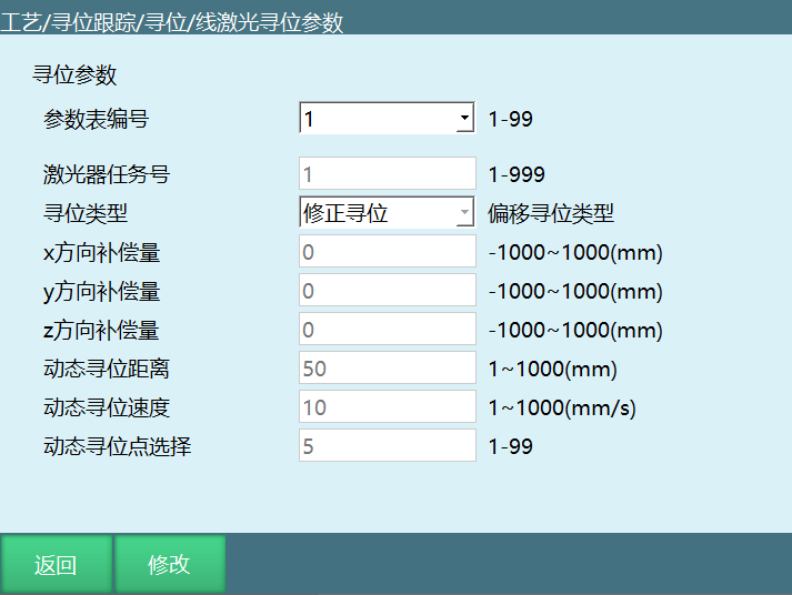
Specialized parameters
The iNexBot system supports up to 99 sets of process parameters, allowing free switching and copying between each set. The laser task number corresponds to the laser manufacturer's parameter number. The parameter settings are minimal and simple, and can be fully customized according to requirements.
Laser Tracking
Laser tracking refers to installing the laser vision sensor on the front end of the welding torch for detection, and calculating the position coordinates of the sensor measurement point through the pre-calibrated positional relationship between the laser vision sensor and the welding torch.
During the welding process, the teaching position of the robot is compared to the detection position of the sensor, and the positional deviation of the corresponding point is calculated. When the welding torch, lagging behind the laser line, reaches the corresponding detection position, the deviation is compensated onto the current welding trajectory, achieving the goal of correcting the welding trajectory.
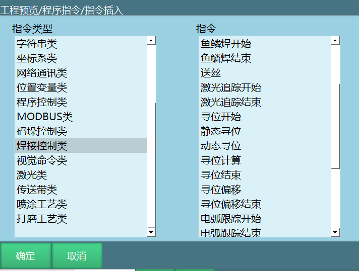
Specialized laser tracking instructions
The laser tracking instructions are minimal. You only need to determine the start point using a linear or point-to-point instruction and then insert the desired trajectory to be tracked between the start and end points. Laser tracking supports straight line tracking, irregular trajectory tracking, curve tracking, and arc tracking. It can track any target within the range of the laser scanner with high accuracy of ±0.5mm.
Positioning and tracking can also be used together to determine the precise start point for tracking.
Laser tracking is commonly used when weld seams are irregular and not a straight line. It can use a straight line to determine the start and end points. During the process, as long as the laser can be detected, the tracking can continue. If it cannot be detected, the robot will pause its operation.
Laser tracking is typically employed in cases where weld seams are irregular and not a complete straight line. In such cases, a straight line is used to determine the start and end points. As long as the laser is able to detect the weld seam, the tracking can continue uninterrupted. If the weld seam is not detected by the laser, the robot will pause its operation.
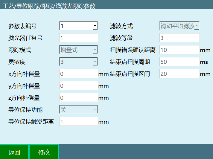
Specialized laser tracking parameters
Laser tracking also has its own independent parameters. It supports 99 sets of parameters, allowing free switching and copying between each set. It includes all commonly used parameters and allows custom adjustment of offset, scanning parameters, etc., ensuring tracking stability.